The AutoConstraint command is useful in re-using existing entities or when turning existing 2D entities into a profile. When you use this command, the program automatically applies certain constraints. The constraints applied are determined by the selections under Automatic constraints on the Profile category of the Document Properties. Also, when you sketch lines, the program determines whether those lines are vertical, horizontal, or tangent when you apply constraints based on the Angular value set in Tolerance, in the Profile category quoted above.
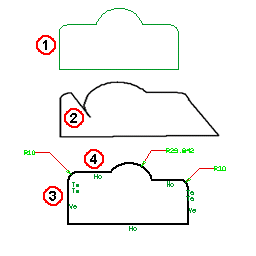
See the following illustrations and the notes related to the different reference numbers:

| 1. | Existing 2D entities are used to create a profile. |
| 2. | The degree of freedom of the 2D line entity allows a loss of the basic profile shape when it is repositioned. The resultant modification shows a loss of tangency and other deformations that would be undesirable. |
| 3. | By applying the AutoConstraint command, the basic shape is maintained when editing the profile. |
| 4. | The degree of freedom of the 2D line entity, when repositioned, does not change the basic shape of the profile due to the locking constraints. |
Does AutoConstraint work well? Yes, it will add the needed constraints for the specific situation as set up under Document Properties (i.e. tangency conditions, horizontal, vertical, radii). However, it is not supposed to fully constrain the profile, but to only add the essential ones. This leaves you the freedom to add the ones that you need to pursue your design intent. Remember that you are not forced to fully constrain your profile.
Sometimes you can obtain an over constrained profile where you will need to delete some unwanted constraints (for instance, Radius). Also, pay attention to the fact that AutoConstraint may change quasi-vertical lines (i.e. 1 deg) in vertical (0 deg). This depends on the tolerance setting as described above.