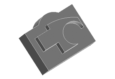
Construction lines have been used to draw the exact desired shape, as if you were working just in 2D with any 2D product: very fast since no constraints need to be added.
Construction lines have been deleted or hidden (see Create valid 2D profiles for creating 3D models). Add a linear protrusion. Changes on the face the profile has been drawn onto, make the Work Plane, and so the profile and the protrusion change accordingly (not the shape, just the position).
However, changes on the base solid don't reflect on the profile, nor on the protrusion, since no rules, no constraints have been added. Therefore the position of the protrusion is not defined, is not predictable. This approach is good when later changes are not needed.
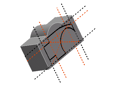
On the other hand, if changes are needed and specific design intent needs to be preserved, we have to insert some intelligence on the shape, by means of constraints. See the following example. To do this, making use of the 2D Profile environment is probably the way to go for, since most constraints will be added automatically. However, keep in mind that, in the think3 application, you can add constraints whenever you want in the design process.
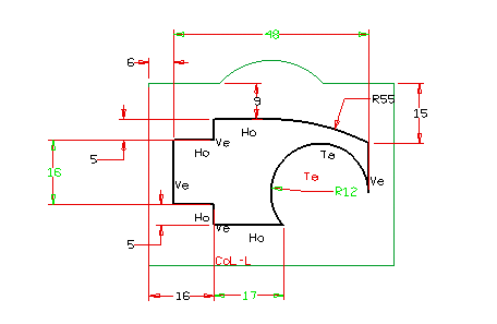
Here are the constraints we want (accordingly to the desired design intent).
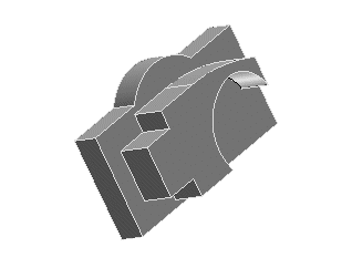
Changing the base solid the protrusion behaves as desired.
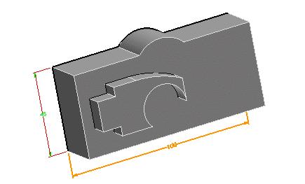
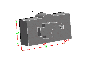
The protrusion shape can also be changed by means of dimensions.