![]()
Insert MoldDesignMulti-Cavity Layout
The Multi-Cavity Layout command enables you to create multiple copies of derived components, starting from the selection of components as initial references. The initial references need to be X-reference components, usually core & cavity workpieces. This helps the generation of multi-cavity mold layouts.
The resulting components are X-references components, stored in the same folder as the assembly of the core & cavity workpieces and sticking to the following naming rules:
<INITIAL_XREF>_layout_<layoutnumbering>.e3
where <layoutnumbering> is a number related to layout copies as sequences like the following:
part1_layout_F1.e3
part1_layout_F2_1.e3
part1_layout_F3_S1.e3
part1_layout_F1_layout_F1.e3
etc
.
The Multi-Cavity Layout command generates a history based event that can be redefined through the model structure.
More than one Multi-Cavity Layout is allowed in the same assembly, by selecting X-reference components from a previous Multi-Cavity Layout event.
| Fit | Enables you to specify the number of copies and the linear or angular extension in which to specify those copies. |
| Fill | Enables you to specify the linear or angular step between the original and the first copy, and the linear or angular extension in which to fill those copies (with the number of copies determined by the number required to fill the extension). |
| Fixed | Enables you to specify the number of copies and the linear or angular step between the original and the first copy. |
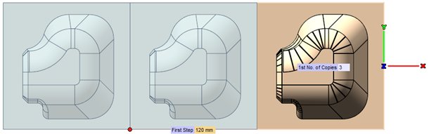
| Linear | Creates a linear pattern in one direction. You are enabled to choose the direction as the one of an existing Line, or as the one defined by 2 points, or as parallel to X, Y or Z. |
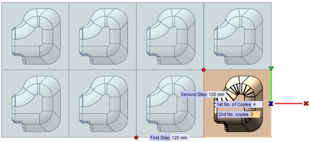
| Linear-Linear | Creates a linear pattern in two directions. You are enabled to choose the directions as the ones of an existing Line, or as the one defined by 2 points, or as Parallel to X and through point, Parallel to Y and through point, or Parallel to Z and through point. |
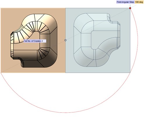
| Angular | Creates an angular pattern about a single axis. You are enabled to choose the axis of rotation as an existing Line, or as the one defined by 2 points, or as X, Y or Z. |
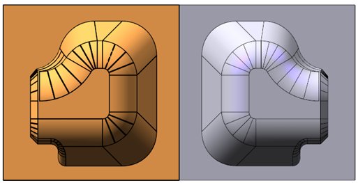
| Mirrored | copies a core&cavity by mirroring it about a plane of symmetry. You are enabled to choose the method used to define the plane of symmetry: On Face - on an existing face; 3 Points - on a plane passing through three points; Plane - on an existing plane; Through axis & point - on a plane passing through an existing line and a point, or passing through the line defined by two points and a third point; Perpendicular to axis & through point - on a plane perpendicular to an existing line and passing through a point, or perpendicular to the line defined by two points and passing through a third point. |
| Note
The Mirrored Type generates mirrored derived copies of the selected components, so that the resulting core and cavity shapes will be mirrored copies of the original parts.
Current command limitations:
|
Examples: