MicroScribe Input Device
The MicroScribe-3D product line enables you to construct detailed computer models by simply tracing the surface features of real physical objects. This document describes how to use the MicroScribe input device inside think3 applications.
Overview
The MicroScribe device can be used in think3 applications to digitize 2D/3D points on template models for reverse engineering goals. think3 applications use the Inscribe driver, released by the MicroScribe device manufacturer. Inscribe must be installed and running to digitize points. Once you have added geometric points to a model, you can use them as a reference to create surfaces and solids.
- Inscribe is a companion program for Immersion MicroScribe Desktop Digitizing Systems. It enables the MicroScribe to be used for 2D or 3D data acquisition.
- InScribe is a stand-alone utility that runs simultaneously with other Windows programs. This utility translates the XYZ position of the MicroScribe into alphanumeric text and records this information in compatible Windows programs.
Inscribe.0 offers many features including: The ability to author custom format strings and save them.
- A custom reference feature allows users to define the origin and direction of the X and Y-axes within the physical workspace.
- Scan Planes allow data collection on planes that 'slice' through objects.
- MicroScribe Mouse allows the MicroScribe to function as a mouse when the stylus enters a mapped region in the workspace.
- An Auto Plot feature allows users to capture data at defined intervals of distance.
Before using them in think3 applications, the MicroScribe device and the Inscribe driver must be installed according to the manufacturer documentation.
Starting up the MicroScribe device
Inscribe is an utility from Immersion Corporation. It formats the XYZ data from the MicroScribe so that various programs are able to accept it. To use the MicroScribe input device inside think3 applications, you need to properly configure it.
Configuring Inscribe
| 1 |
Unzip all the files you need to configure Inscribe. Please take into account the version of the Inscribe utility might be different from the one displayed in this document, but the configuration procedure is substantially the same. |
| 2 |
Double-click Setup.exe ( ) and follow the guided installation steps. Once the installation is over, the Immersion Inscribe icon will be displayed on your desktop: ) and follow the guided installation steps. Once the installation is over, the Immersion Inscribe icon will be displayed on your desktop:

|
| 3 |
Run Inscribe by double-clicking the Inscribe Immersion icon. The following dialog box is displayed:
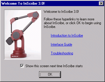
From this dialog box you can access both the documentation and the troubleshooting section.
- Click OK. The MicroScribe Configuration dialog box is displayed:
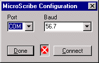
- Click Done to go on (the default values displayed in the dialog box are generally the right ones to be used). The Immersion Inscribe toolbar is displayed:

|
| 4 |
Click the Format Strings button:

The Immersion Configuration dialog box is displayed:
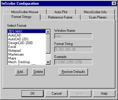
|
| 5 |
In the Select Format list of the Format Strings tab, select:
- ThinkDesign for 3D points or
- thinkdesign 2D for 2D points
If the above said strings are not there...
the think3 application installation procedure adds the thinkdesign and thinkdesign 2D to the Format list. Any way, if the two said strings should not be displayed in the list, you can proceed as follows:
- Select Add.... The Add Format String dialog box is displayed. In the Enter the name of the new Format String box, type thinkdesign:
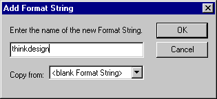
- Click OK.
- In the Window Name box of the Format Strings tab of the Inscribe Configuration dialog box, type: thinkdesign
- In the Format String box, type the following string:
|%0.4f %0.4f %0.4f\n
checking that the first character is "|" and the last ones are "\n".
- The Save Changes? dialog box is displayed:
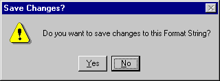
Select Yes.
The procedure can be repeated for 2D input points specifying the thinkdesign 2D Format String Name, the thinkdesign 2D Window Name and the |%0.4f %0.4f 0\n Format String. |
If the thinkdesign or thinkdesign 2D strings are already there, check the Window Name is thinkdesign and the Format String is |%0.4f %0.4f %0.4f\n, beginning with "|" and ending with "\n".
|
| 6 |
Select OK.
|
| 7 |
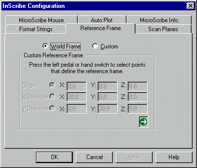
Select the Reference Frame tab:
|
| 8 |
Select either World Frame or Custom:
| World Frame |
uses the default reference frame the MicroScribe establishes at start up |
| Custom |
enables the user to define where the origin and X- and Y-axes are in the physical workspace. For more information about Custom Reference Frames see Inscribe help. |
|
| 9 |
Select the MicroScribe Info tab to define the unit of measure:

|
Using the MicroScribe device inside think3 applications
Using the MicroScribe input device, you can simply input points to the think3 application when required, as well as uniformly space points along a curve or create 2D cross section curves of 3D objects.
Data input in think3 applications
Once Inscribe is configured, you can run the think3 application and simply select commands requiring point input, such as, for example, the ones you use for creating point entities, lines, polylines, spline curves, arcs, etc.
You will be able to input the required points using the MicroScribe device.
Move the focus onto the think3 application window before inputting points ...
Since Inscribe sends coordinates to the focused window, ensure the focus is on the think3 application main window: to move the input focus onto it, click on the window frame or on the document title banner.
If the focus is not on the think3 application window, none of the points you select will be acquired by the think3 application.
|
Using the Auto Plot feature
The Auto Plot feature enables users to capture data at defined distance intervals.
It is ideal for uniformly spacing points along a curve. It works well with the Lines and
Polyline command.
To enable the Auto Plot feature, proceed as follows:
| 1 |
Select MicroScribe Info (  ) in the Immersion InScribe toolbar. ) in the Immersion InScribe toolbar.
|
| 2 |
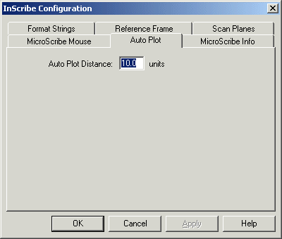
When the Inscribe Configuration dialog box is displayed, select the Auto Plot tab.
|
| 3 |
In the Auto Plot Distance text box, type the distance value to be applied between each couple of captured points:
 |
| 4 |
Select OK. |
| 5 |
Select Auto Plot ( ) in the Immersion InScribe toolbar. It will darken to show it is enabled ( ) in the Immersion InScribe toolbar. It will darken to show it is enabled ( ). ). |
| 6 |
Hold down the right pedal or hand switch button and move the MicroScribe stylus over the object you are digitizing. A point will be taken each time the tip travels the distance you specified. It is important to not move the stylus too quickly when collecting points, or some may be missed. |
| 7 |
When you are done using Auto Plot click on the corresponding icon to deactivate it. The icon will lighten to show it is no longer in use. |
| 8 |
Follow the previous steps to set and use a different distance. |
For more information on using this feature see the help files of Inscribe.
Please note:
Auto Plot only works when the MicroScribe Mouse feature in Inscribe is OFF. |
Using the Scan Planes feature
The Scan Planes feature allows users to create 2D cross section curves of 3D objects. The user defines a series of virtual planes. Then, each time the MicroScribe stylus passes through one of the planes, data is collected.
| 1 |
Select MicroScribe Info (  ) in the Immersion InScribe toolbar. ) in the Immersion InScribe toolbar.
|
| 2 |
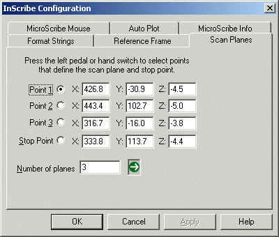
When the Inscribe Configuration dialog box is displayed, select the Scan Planes tab to see the feature options.
|
| 3 |
This feature defines the first plane via 3 input points (Point 1, Point 2, Point 3). Then, an axis is defined by a fourth point (Stop Point). You can define the Number of planes along the axis.
|
| 4 |
A minimum of two planes is required to use this option. If you need data on only one plane, define the stop point well past the area you are digitizing in. |
| 5 |
Select Scan Planes ( ) in the Immersion InScribe toolbar. It will darken to show it is enabled ( ) in the Immersion InScribe toolbar. It will darken to show it is enabled ( ). ). |
For more information on this feature see the help files of Inscribe.
Helpful Tip:
Start by collecting points before attempting to collect curves. Collecting points is generally easier - there is no need to worry about order or number. It is good to get a feel of how the feature works before trying to collect curves. |
Using other input methods in conjunction with the MicroScribe
It is possible to use all other available input methods and devices in conjunction with the MicroScribe during all the think3 application commands.
This is very helpful when you need to snap to exact points with the mouse, send voice commands through the speech recognition, transform the scene using keyboard or 3D Input devices.
Using Non-standard Tips with the MicroScribe-3D
The following notes are intended for MicroScribe users who wish to use any tip other than the Standard Point Tip to digitize with. The Standard Point Tip is shipped with all MicroScribe units. Any type of tip other than the Standard Point Tip is considered to be nonstandard, or custom. Immersion sells Extra Fine and Standard Ball Tips for use with MicroScribe-3D digitizers. For further details see http://www.immersion.com/digitizer.
The Importance of Software Support for Tip Compensation
To use any tip other than the Standard Point or Extra Fine models, the software you are digitizing in needs to support tip compensation. If the program does, it will use a file called armdll32.dll. To find out if your software is using this file choose Find from the Windows Start menu. Search for armdll32.dll on any hard drives that you have your 3D software on.
If the search reveals that the armdll32.dll file is in the program folder of your 3D software, then you can successfully use a non standard tip with your MicroScribe-3D. If the file is not there, you will not be able to use a tip other than the Standard Point or Extra Fine tips on your digitizer.
InScribe, the free utility from Immersion, does support tip compensation. InScribe runs in the background of Microsoft Windows O.S., entering X, Y, Z coordinate values directly into many Windows applications each time the input device is activated.
There are two versions of InScribe – Inscribe2 and Inscribe. These directions will first cover how to use a nonstandard tip with Inscribe, the newest version of the utility.
It is recommended to use Inscribe with nonstandard tips, as the process is simpler than that of Inscribe2.
Types of Tips
As stated previously, Immersion supplies three different types of tips for MicroScribe users: Standard Point, Extra Fine, and Standard Ball. Each type is shown below:
 |
 |
 |
| Standard Point Tip |
Extra fine Tip |
Standard Ball Tip |
Using the Extra Fine Tip
The Extra Fine Tip is the same length as the Standard Point Tip. Because of this, use of the Extra Fine Tip does not require software that supports tip compensation (for more on this see the Importance of Software Support for Tip Compensation section above).
Although the same length, the Standard Point and Extra Fine Tips cannot be used interchangeably when powering on the MicroScribe. Once the MicroScribe has been started you may switch out the Standard Point for the Extra Fine Tip.
Using the Standard Ball Tip
The Standard Ball Tip is 0.242 inches shorter than the Standard Point Tip. Please note, this measurement is to the center of the ball. Therefore, to get completely accurate surfaces your software will need to compensate for a uniform offset in both distance and direction.
This differs from the previously discussed requirement for software support for tip compensation. Consult the manuals that came with your 3D software to see if curve, line, or surface offsetting is supported in your package.
Using Other Custom Tips
If you are using a tip other than those outlined above, measure the exact difference between the Standard Point Tip and your tip in inches. You will need to know this difference to use the custom tip compensation feature of both Inscribe and Inscribe2.
Technical Support for Non standard Tips
Although Immersion encourages you to customize your MicroScribe to be the most productive for your specific workflow, please take precautions when using tips other than those outlined in this document. Prior to fabricating your own tip please contact us (http://www.immersion.com/digitizer/contact) to get additional specifications, including the thread size required for tips. We usually do not provide technical support for issues regarding the use of tips other than the three explained above.
Powering on the MicroScribe Properly
Whenever you wish to use a non standard tip with the MicroScribe-3D it is very important that the digitizer is powered on in the ‘Home Position’ with the Standard Point Tip in place.
The Home Position is important because it is used by the MicroScribe as a reference for calculating and establishing an origin (0X, 0Y, 0Z) and reference coordinates in the 3D workspace. A tip other than the Standard Point Tip will skew these calculations and result in inaccurate data.
If you plan on digitizing with an Extra Fine Tip, the MicroScribe still needs to be powered on in the home position with the Standard Point Tip. However, the D5Delta value in mstip.dat does not need to be changed from zero (this is explained below).
After powering on the MicroScribe in the Home Position, you may simply switch tips by unscrewing the chrome tip in a counter-clockwise direction and screwing the replacement firmly in.
Directions for Using a Non standard Tip with InScribe3
- Ensure the MicroScribe is properly connected to the PC.
- Power on the MicroScribe in the Home Position with the Standard Point Tip in place.
- Install and launch Inscribe.
- If InScribe is communicating properly with your PC the interface will appear - a horizontal row of eight icons. In the left-most icon a green circle will show, signifying communication.
- If you do not see the interface described above check the Troubleshooting section of the InScribe help files for tips on connection.
- Click on the MicroScribe Info icon, second from the right.
- In the right portion of the screen check the Use custom tip delta option. In the field below type in the delta length for the custom tip.
- If using the Extra Fine Tip leave the value at zero. If using the Standard Ball Tip change the value to 0.242.
- If using any other type of custom tip you will need to calculate the delta length. Follow these steps to do so:
- Measure the exact difference between the Standard Point Tip and your tip in inches. The result should be entered in the Custom tip delta area.
- If the tip is longer than the Standard Point Tip, the value should be entered as a negative; if it is shorter the value should be positive.
- Click OK to exit out of the MicroScribe Info panel.
- Replace the Standard Point Tip of the MicroScribe with the nonstandard one.
- When you are finished using the nonstandard tip remember to change the Custom tip delta length in the MicroScribe Info panel back to zero.
 ) and follow the guided installation steps. Once the installation is over, the Immersion Inscribe icon will be displayed on your desktop:


 ) in the Immersion InScribe toolbar.
 ) in the Immersion InScribe toolbar. It will darken to show it is enabled (
 ).
).
 ) in the Immersion InScribe toolbar. It will darken to show it is enabled (
 ).
).

