| 1 |
Load file "GLM_Symmetry.e3"
(Courtesy of STS — www.vercarmodel.com — Gruppo Vercarmodel Via I° Maggio 2/4 10043 Orbassano (TO) - ITALY)
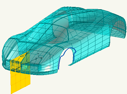
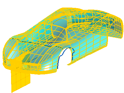
Start the Advanced GSM command and select the solid.
|
| 2 |
Under More Options, select the
Copy check box.
|
| 3 |
Under Matching, select
Curves in the
Matching drop-down list.
|
| 4 |
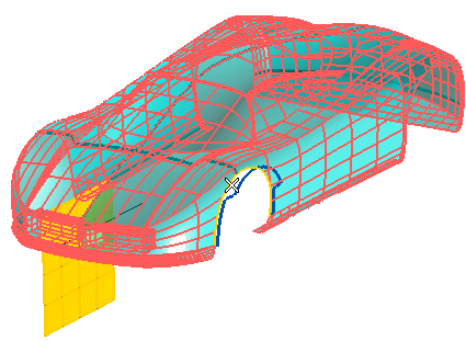
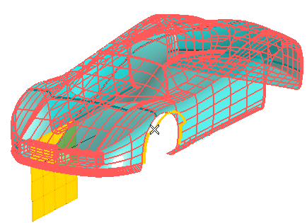
Under Group 1, click on Initial Curves and select the edge of the fender on the right, as in the following illustration:
Then click on Target Curves and select the blue curves:
|
| 5 |
In order to apply the same controlled modification also to the fender on the right, select the Symmetry box under
More Options. In the
Reference Plane drop-down list select
Datum plane and click on the yellow plane.
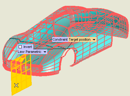
Defining the symmetry plane
The Reference Plane drop-down list enables you to choose the selection method for the symmetry plane:
| On Face |
A face of a solid to be selected (Face). |
| 3 points |
The plane univocally identified by three points to be specified (3 points). |
| Datum plane |
An existing datum plane to be selected (Plane). |
| Through axis & point |
A plane through an axis to be selected (Axis, see "
How to define an axis or a line") and a point (
Point), both to be specified. |
| Perpendicular to axis & through point |
A plane orthogonal to an axis (Axis, see "
How to define an axis or a line") and through a point (
Point), both to be specified. |
| Coefficients |
A plane defined through the coefficient values of its cartesian equation (Ax+By+Cz+D=0), to be specified in the respective mini-dialog boxes (Coeff. A,
Coeff. B,
Coeff. C,
Coeff. D), and through a point to indicate (
Point). |
|
|
| 6 |
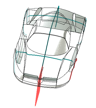
Click the Preview button (  ) to display a preview of the result: the modification has been applied also to the fender on the right. ) to display a preview of the result: the modification has been applied also to the fender on the right.
|
| 7 |
Click  or or  to confirm your selections modify the shape of the object. to confirm your selections modify the shape of the object.
Click  to discard your changes. to discard your changes. |


 ) to display a preview of the result: the modification has been applied also to the fender on the right.
 or
or  to confirm your selections modify the shape of the object.
 to discard your changes.