| GRA NPBUF | ——— | Sets maximum number of instructions per path (PostScript) |
SYNTAX
GRA NPBUF max_num
ARGUMENTS
| max_num | integer greater than 10, defining the maximum number of instructions contained in a path (default 1200). |
DESCRIPTION
Defines the maximum number of graphics instructions managed for PostScript in a path, i.e.: in the device's temporary graphics buffer.
Every system has a maximum limit for the number of graphics instructions contained in one path. To optimize functioning, set the max_num value closest to this limit.
To identify the limit value, refer to the hardware documentation supplied
by the manufacturer.
| GRA ODVC | ——— | Manages serial port configuration |
SYNTAX
GRA ODVC [opt [baud_rate [parity [data [stop_bit [timeout [perm_flg]]]]]]]
ARGUMENTS
| opt | option which may assume the following values:
|
| baud_rate | defines the serial line baud rate; may assume these
values:
|
| parity | defines the type of parity check, which may be:
|
| data | defines the number of data bits for the port, which may
be:
|
| stop_bit | defines the number of stop bits, which may be:
|
| timeout | defines the timeout time, in tenths of a second. The value 0 indicates an infinite timeout. The default is 20 tenths of a second. |
| perm_flg | flag which can assume the following values:
|
DESCRIPTION
Switches On/Off automatic serial port configuration for output devices (plotters and printers).
It may be useful to switch Off this function if the configuration of the device in question does not correspond to that envisaged.
If automatic configuration is On, you can manage the serial port parameters: the baud rate, parity, number of data bits, stop bits, the timeout period and the permanence of the configuration.
The code without arguments is equivalent to:
GRA ODVC ON 9600 0 8 1 20 1.
| See also: | GRA ODVT
ODEV |
| GRA ODVL | ——— | Defines output device limits |
SYNTAX
| GRA ODVL | x1 y1 x2 y2
[un_meas_1] | dx1 dy1 dx2
dy2 un_meas_2
|
ARGUMENTS
| x1, y1 | integers which set the absolute coordinates of the bottom left-hand corner of the rectangle defining the working area |
| x2, y2 | integers which set the absolute coordinates of the top right-hand corner of the rectangle defining the working area |
| dx1 dy1 | integers which set the coordinates relative to the hardware limits of the bottom left-hand corner of the working area. Positive values refer to the bottom left-hand hardware limit, negative values refer to the top right-hand hardware limit. |
| dx2, dy2 | integers which set the coordinates relative to the hardware limits of the top right-hand corner of the working area. Positive values refer to the bottom left-hand hardware limit, negative values refer to the top right-hand hardware limit |
| un_meas_1 | unit of measure for the absolute limit coordinates; values allowed
and meanings:
PI limits expressed in units of the device (default); |
| MM | unit of measure in millimeters; recalculated in units of the device depending on the resolution |
| un_meas_2 | unit of measure for the relative limit coordinates; values allowed
and meanings:
RP unit of measure in units of the device; RM unit of measure in m,illimeters. |
DESCRIPTION
Defines the active area of the output device, i.e., the area in which you intend to draw.
The definition may be absolute or relative to the device's hardware limits, expressed in units of the device or in m,illimeters. If the limits defined exceed those of the hardware, they are brought within the latter.
The use of m,illimeters as the unit of measure (whether absolute or relative) allows you to define the areas irrespective of the device used.
| See also: | GRA
FORMD GRA ODVT |
| GRA ODVSC | ——— | Defines output device closing string |
SYNTAX
GRA ODVSC string | @name
ARGUMENTS
| string | string transmitted to the device at closure. |
| @name | name of the file containing the strings to be
transmitted to the device at its closure. |
DESCRIPTION
Defines a string of characters to be transmitted to the output device (plotter) at its closure (only for devices which have this function: for details on how to use this parameter, refer to the documentation about the device).
You can include special characters in the string in symbol form, as follows:
Where allowed by the device used, you can use a closing file, by placing the character @ before the name of the file; the latter is opened and transmitted to the device line by line in place of the string.
| See also: | GRA
ODVT PRC |
| GRA ODVT | ——— | Defines type of output format (device) used |
SYNTAX
GRA ODVT output_type
ARGUMENTS
| output_type | mnemonic identifier for type of graphic output format. The default depends on the installation configuration: it is usually HP-GL/2. |
DESCRIPTION
Allows you to define the type of format to be used for the graphics output.
If you indicate an output which is not allowed, an error indication appears.
If you do not specify the type of format, the program always assigns a default type, depending on the installation configuration. The mnemonic identifiers for the various devices appear at the end of this description.
Note: the definition of the type of format must precede the other configuration commands for the same device in the initialization file. The same applies if you use the code as an option in the run string.
Wherever the hardware/software configuration does not allow you a choice, the
default type is already correct, therefore, the command has no impact.
| See also: | ODEV |
The following tables show the values allowed for types of output device/format:
CALCOMP
HP-GL
Raster
PostScript
MS-Windows environments
| MWPRINTER | output to Print Manager |
| MWMETAFILE | output to MS-Windows Metafile |
| MWCLIPBOARD | output to Clipboard |
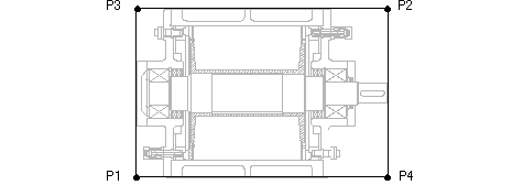
| GRA P1P2 | ——— | Defines reference points P1 and P2 |
SYNTAX
GRA P1P2 x1 y1 x2 y2
ARGUMENTS
| x1, y1 | integers which define the coordinates of point P1. |
| x2, y2 | integers which define the coordinates of point P2. |
DESCRIPTION
Redefines the position of points P1 and P2 and so also the working dimensions of the sheet for plotting (in device units of measure).
For the plotters which manage it, the frame step (in device units of measure) remains fixed. Each plotter has its own specific frame step linked to the default values of P1 and P2,obtained with the plotter on line and GRA SHP1P2.
You may have to set a frame step when plotting with framing on file (plotter off line). In this case, the
program cannot poll the plotter for the specific frame step. The values of P1
and P2 to be specified are those obtained as above.
| See also: | FRA
GRA SHP1P2 |
| GRA PNTM | ——— | Defines point drawing mode |
SYNTAX
GRA PNTM HW | SW [symb [dim]]
ARGUMENTS
| HW | the point entity is drawn in device dependent mode (i.e.: in a hardware mode which depends on the device used); |
| SW | the point entity is drawn in software dependent mode, with a marker. |
| symb | integer which defines the symbol used to draw the point entity (default 1); allowed values: 1:4. |
| dim | integer which defines the size expressed in device dependent units of the symbol used for the point entity (default 2); values allowed ³ 1. |
DESCRIPTION
Defines the point entity drawing mode.
The description of the points via software depends on the symbol symb selected, the description in hardware mode depends on the device used.
The arguments are positional; the character "#" allows
you to leave the current value of the respective parameter unchanged.
| GRA PWIDTH | ——— | Defines thickness to be associated to pensline widthline weight |
SYNTAX
GRA PWIDTH {pen thickness [unit]}
ARGUMENTS
| pen | integer which identifies the colour (pen) to which the thickness sp must be associated; values allowed -1:256. |
| thickness | real number which identifies the thickness associated to the colour pen; values allowed -256:256; |
| unit | unit of measure;
values allowed and meanings:
Default:0. No thickness. |
DESCRIPTION
For each colour index (0:255), allows you to define a thickness (line weight or line width) in various forms.
If pen=-1 the thickness specified is assigned to the entire colour table.
The presence of unit indicates that you must multiply the thickness value by 1 (MM), by 10 (CM) or 25.4 (IN).
If thickness < 0, irrespective of the thickness management mode (GRA MWIDTH) is considered to be in units of the device.
If thickness > 0 and the thickness management mode is in units of the device (GRA MWIDTH 1), only the whole part of the number expressing the thickness in units of the device is considered.
Thickness management may not be available on all
devices.
| See also: | GRA
COLCH GRA MWIDTH GRA NCOLS GRA ODVT RPL |
| GRA ROPS | ——— | Defines number of lines per block (Raster) |
SYNTAX
GRA ROPS num-line
ARGUMENTS
| num-line | integer which indicates the number of lines (scanlines) contained in each block (strip) (default 0); values allowed 0:32000. |
DESCRIPTION
Allows you to define, in TIFF format output for Raster devices, the number of lines (scanlines) which constitute each block (strip).
If num-line=0 the program
calculates the value so that the scanlines per strip that are not compressed are almost 8 Kbytes
(value selected in accordance with the data in the Adobe manual).
| See also: | GRA ODVT |
| GRA ROTATE | ——— | Sets drawing angle of rotation |
SYNTAX
GRA ROTATE angle
ARGUMENTS
| angle | integer defining the angle of rotation; values allowed -360:360 (normally, but there are restrictions depending on the output device/format). |
DESCRIPTION
Allows you to rotate the drawing through an angle to adapt it to the paper size used.
Not all devices allow rotation unless you adjust the plotter panel directly. The following values are allowed depending on the output formats/devices (GRA ODVT):
The 90 degree rotation is also useful in cases of mixed
output (raster and vector) to obtain the same orientation of the x and y axes.
| See also: | GRA
ODVT ROR |
| GRA SHDEV | ——— | Displays data relative to graphics devices |
SYNTAX
GRA SHDEV
DESCRIPTION
Displays data relative to the graphics devices
(diagnostics) on-screen.
| GRA SHP1P2 | ——— | Displays reference points P1 and P2 |
SYNTAX
GRA SHP1P2
DESCRIPTION
Used with a plotter on line, when running GBPLO allows you to display the position of points P1 and P2 which represent the size of the plotting area, also linked to the framing step (if managed by the plotter).
This data allows you to use the off line framing (FRA)
mode, specifying the dimensions of the frame step for that paper size with the
code GRA P1P2.
| See also: | FRA GRA P1P2 |
| GRA STRIP | ——— | Manages leading and trailing blanks on drawing (Raster) |
SYNTAX
GRA STRIP [option]
ARGUMENTS
| option | may assume the following values:
|
DESCRIPTION
On raster devices, enables the removal of any blank lines (scanlines) present when the window supplied exceeds the window actually occupied by the drawing.
The ON mode is also useful to reduce insignificant data
when you want to place other data before or after the drawing.
| LAN | ——— | Defines I/O language |
SYNTAX
LAN language
ARGUMENTS
| language | I/O language code. One of the
following values:
|
DESCRIPTION
Allows you to select the language in which the program
I/O messages will be displayed.
| LSI | ——— | Defines symbol library |
SYNTAX
LSI library
ARGUMENTS
| library | pathname of the symbol library file. If you do not specify the directory, GBPLO searches the current drawing directory defined with DRC. |
DESCRIPTION
Allows you to define the library to be used to resolve the occurrences of symbols present in the drawing.
The possibility of changing the current symbol library may prove very useful when printing files containing symbols which, although maintaining the same name, assume a different graphic appearance in different contexts.
For example, the same drawing may contain symbols to be
printed according to European standards and American standards: this option
allows you to print both versions of the drawing by simply specifying the two
different libraries, without changing the drawing file.
| See also: | DRC |
| MIS | ——— | Defines drawing unit of measure |
SYNTAX
MIS unit_code
ARGUMENTS
| unit_code | numeric code identifying the drawing
unit of measure:
|
DESCRIPTION
Allows you to define the drawing unit of measure,
selecting it from the units of the metric - decimal system or imperial measures.
| MOD | ——— | Sets run mode |
SYNTAX
MOD mode_code
ARGUMENTS
| mode_code | string identifying the run
mode: INTER constrains interactive mode BATCH constrains non-interactive (batch) mode. |
DESCRIPTION
Allows you to constrain the interactive mode (see
section 2.10) even if you specify at least one of the main parameters (i.e.: all
data requested), or batch mode (i.e.: no interactive questions) even if you do
not specify any of the main parameters.
| MSG | ——— | Defines message file |
SYNTAX
MSG pathname
ARGUMENTS
| pathname | pathname of the message file. |
DESCRIPTION
Allows you to define the pathname of the message file. This is a file for internal use, necessary for running GBPLO and must not be modified.
You can specify the pathname in relative form, even
using symbolic names defined with the DEF directive.
| See also: | DEF |
| NCO | ——— | Sets number of copies |
SYNTAX
NCO num_copies
or:
GRA NCOP num_copies
ARGUMENTS
| num_copies | integer defining the number of copies to be made of the drawing (default 1); values allowed 1:99. |
DESCRIPTION
Defines the number of copies of the drawing required, on
output devices with this function.
| See also: | AVA
GRA MERGE GRA ODVT |
| NPE | ——— | Sets pens available for plotting |
SYNTAX
NPE plot_pens
ARGUMENTS
| plot_pens | number of pens which the plotter puts on line. Default: 8. |
DESCRIPTION
Allows you to define the total number of pens which the
plotter must put on line for the current plotting session.
| ODEV | ——— | Defines output device name |
SYNTAX
ODEV name
or:
GRA ODVN name
ARGUMENTS
| name | name of the symbol file associated to the output device or name of the file to which plotting is to be directed. |
DESCRIPTION
Defines the name of the symbol file which identifies the current output device or, if the plotter is off line, indicates the name of the file to which plotting is to be directed.
The GRA ODVT code sets a
default name depending on the hardware, suitable for a standard configuration.
| See also: | GRA
GFILE GRA ODVT |
| PPE | ——— | Sets pen position at end of plotting |
SYNTAX
PPE position_code
ARGUMENTS
| position_code | symbolic code identifying the pen
position after plotting:
|
DESCRIPTION
Allows you to define the pen position at the end of plotting. That is to say, upon completion of the drawing, GBPLO moves the pen to the position indicated.
This directive is useful if you want to print two or
more drawings on the same sheet, merging them in an alternative mode to that of
run option -COM.
| PRC | ——— | Defines output device initialization string |
SYNTAX
PRC string | @name
or:
GRA ODVSI string | @name
ARGUMENTS
| string | string transmitted to the device when it is opened. |
| name | name of the file containing the strings to be transmitted to the device when it is opened. |
DESCRIPTION
Defines a string of characters to be sent to the output device (plotter) when it is opened, if the devices has this function; for details on how to use this parameter, refer to the documentation about the device used.
The string entered substitutes that normally used (if present).
You can include special characters in the string in symbol form, as follows:
Where allowed by the device used, you can use an opening file, by placing the character @ before the name of the file; the latter is opened and transmitted to the device line by line in place of the string.
| See also: | GRA
ODVSC GRA ODVT |
| QAL | ——— | Enables printing of alternative dimension format |
SYNTAX
QAL alternative_code
ARGUMENTS
| vfm | code which controls the display of alternative dimension formats. This is a 32 bit mask in which each bit relates to the corresponding alternative (bit 1 « first alternative, bit 2 « second alternative, etc.). Default: 0 (displays fixed part only). |
DESCRIPTION
In drawings from the GBG DraftMaker environment, allows you to manage the display of alternative parts of dimension formats.
The n-th alternative is the string between the n-th and (n+1)-th alternative format separator ({an} or {An} and {an+1} or {An+1}). To display the n-th alternative, set the n-th bit of the mask to = 1. Set more than one bit to = 1 to simultaneously display corresponding alternatives.
E.g.:
|
|
|
|
|
|
|
|
|
|
|
|
|
|
|
|
|
|
|
|
|
|
|
|
|
|
|
|
|
|
|
|
|
|
|
|
|
|
|
|
|
|
|
|
|
|
|
|
|
|
|
|
|
|
|
|
|
|
|
|
|
|
|
|
|
|
|
|
|
|
|
|
|
|
|
|
|
|
|
|
|
|
|
|
|
|
|
|
|
|
|
|
|
|
|
|
| QDT | ——— | Defines leader limit distance |
SYNTAX
QDT distance
ARGUMENTS
| distance | minimum value of the distance between the normal position of the dimension text and the actual positioning point above which the leader is drawn, measured on the perpendicular which joins the two positions. |
DESCRIPTION
Allows you to define the minimum distance from the measuring line above which the leader connecting the dimension texts whose position is free is drawn.
| QTE | ——— | Sets text print modes |
SYNTAX
QTE codq0 codq1 codq2 codq3 codq4
ARGUMENTS
| codq0...codq4 | list of the five quality codes for the
representation of text:
codq0 font to be used for text with quality 0 to be
codq3 font to be used for text with quality 3. Values 1 to 4 are allowed. codq4 font to be used for text with quality 4. Values 1 to 4 are allowed. |
DESCRIPTION
For drawings form the GBG DraftMaker environment, allows
you to define the fonts to be used for drawing the text according to its quality
attributes.
| QUO | ——— | Defines pens for drawing dimensions |
SYNTAX
QUO pen_text [pen_arrows [pen_tol]
ARGUMENTS
| pen_text | pen (color) with which to draw the dimension text (format) |
| pen_arrows | pen (colour) with which to draw the dimension arrowheads |
| pen_tol | pen (color) with which to draw the dimension tolerances |
DESCRIPTION
For drawings form the GBG DraftMaker environment, allows you to differentiate the colour (pen) of the dimensions from that used to draw other drawing entities.
You can also differentiate the elements which constitute
the dimensions, by assigning different colours to the arrowheads and tolerances.
| QVP | ——— | Defines dimension decimal separator |
SYNTAX
QVP separator
ARGUMENTS
| separator | numeric code
identifying the type of decimal separator to be used when drawing the
dimension text:
|
DESCRIPTION
Allows you to define the decimal separator to be used in dimension texts, also managing the display of insignificant zeros. Example:
QVP 0 => .1234
QVP 1 => ,1234
QVP 2 => 0.1234
QVP 3 => 0,1234
| ROR | ——— | Manages relocation of drawing origin on plotter |
SYNTAX
ROR dx dy
or:
GRA RORIG dx dy [u_measure]
ARGUMENTS
| dx | real number defining the shift in cm along the x-axis. |
| dy | real number defining the shift in cm along the y-axis |
| u_measure | unit of
measure for the shift; values allowed and meanings:
|
DESCRIPTION
Allows you to shift the drawing origin on the plotter before plotting. The current position of the origin depends on the type of plotter: on relative-motion plotters (BGL, Calcomp) it remains at the point occupied by the pen at the end of the previous drawing, whilst on absolute-motion plotters (HP) it remains fixed at the bottom left-hand point of the sheet or at the center of the sheet. Set the shift with great care, since an error may cause the drawing to be off the edges of the sheet or make the drawing previous drawings.
You must use this code when you rotate the drawing on the Calcomp and BGL plotter, since a 90 ° rotation for Calcomp and BGL moves the drawing from the first to the second frames.
Relocating the origin is one way of merging two or more
drawings on the same sheet, this being an alternative to the mode activated with
run option -COM: although the latter is preferable.
| See also: | GRA ROTATE |
| RPL | ——— | Defines plotter resolution |
SYNTAX
RPL resolution
or:
GRA ODVR rx [ry] [DPI]
ARGUMENTS
| rx | real number which sets the resolution along the x-axis: |
| |
| ry | real number which sets the resolution along the y-axis |
| |
| DPI | constrains the unit of measure for the resolution in dots per inch; if you do not specify this, the resolution is considered |
|
DESCRIPTION
For devices which allow different resolutions, defines values other than the default. The default values are determined automatically where possible, or preset according to the output device family.
CALCOMP PCL format
Default is 40 40. Adjust the resolution if the plotter used has a different configuration.
HP-GL and HP-GL/2 format
Default is 40 40.
Raster format
ODVT default (DPI)
HP29xx 90 DPI
HP22xx 90 DPI
PCL3 300 DPI
PCL5 300 DPI
HPRTL 300 DPI
TIFF 90 DPI
CCRF 406 DPI
IPS 300 DPI
Default is 2400 2400
BGL format
The program sets the values allowed on the basis of the GRA ODVT value
ODVT default
G16xx 20,20
G18xx 40,40
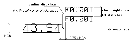
| TOL | ——— | Defines tolerance parameters |
SYNTAX
TOL cenline_dist char_height tol_dist
ARGUMENTS
| cenline_dist | Character height multiplication factor for dimensions which identifies the distance to be set in the drawing between the horizontal line through the center of the tolerances and the horizontal line through the center of the dimension texts |
| char_height | Character height multiplication factor for dimensions which identifies the character height to be used when drawing the tolerances |
| tol_dist | Character height multiplication factor for dimensions which identifies the distance to be set when drawing the tolerances. |
| cenline_dist=0 char_height=0 tol_dist=0.2 |
DESCRIPTION
Allows you to define the tolerance construction parameters.
| UNI | ——— | Specifies UNI table |
SYNTAX
UNI pathname
ARGUMENTS
| pathname | pathname of the file containing a UNI table. |
DESCRIPTION
Allows you to automatically attribute to any dimension
which represents the diameter of a hole or a shaft the tolerances defined in
accordance with UNI standards (UNI 7218-73: selecting tolerance zones for mating
parts recommended to limit the number of tools, test gauges and measuring
instruments). The dimension format which you define must contain indications of
the position and quality of the tolerance (e.g.: FO "{m}a9", FO "{m}JS10",
etc.); you can use the UNI command at any time to add the tolerances contained
in the UNI table from the program to all dimensions defined in this way. Any
tolerances which you specified are substituted by those shown in the table
| VNO | ——— | Defines the unit normal for the view (Eureka) |
SYNTAX
VNO nox noy noz
ARGUMENTS
| nox | component in direction x of the world reference system of the unit normal for the view |
| noy | component in direction xy of the world reference system of the unit normal for the view |
| noz | component in direction z of the world reference system of the unit normal for the view. |
Default
| nox=0 noy=1 noz=0 |
DESCRIPTION
Allows you to define the components of the unit normal
of the xy plane of the reference system of the current view for "e3" files. This
is a z-axis unit vector of the said reference system; given that the latter is a
right-hand orthonormal triplet, it is completely defined once you have also
defined the y unit vector of the reference system (with VUP).
| See also: | VUP |
| VUP | ——— | Defines the unit normal for the view (Eureka) |
SYNTAX
VUP upx upy upz
ARGUMENTS
| upx | component in direction x of the world reference system of the y-axis unit vector of the reference system of the view |
| upy | component in direction xy of the world reference system of the y-axis unit vector of the reference system of the view |
| upz | component in direction z of the world reference system of the y-axis unit vector of the reference system of the view . |
Default
| upx =0 upy =1 upz =0 |
DESCRIPTION
Allows you to define the components of the unit vector
which indicates the direction from the bottom to the top of the view, i.e.: of
the y-axis unit vector of the reference system of the current view for "e3"
files. Since it is a right-hand orthonormal triplet, the said reference system
is completely defined once you have also defined the z unit vector of the
reference system (with VON).
| See also: | VON |