In this mode a rectangular boundary is added to allow the user to pick the view. While printing the view, the boundary is automatically made hidden.
You can display the drawing view either in the form of geometry or a realistic shaded view.
To select the way in which the drawing view is displayed, select one of the options from the View mode area of the Drawing View - Visibility category of the Edit Properties dialog box.
| Geometry only | In this mode, the view has no shading and is drawn as a set of curves. |
|
| Geometry and Image | In this mode, shading is added to the view using a bitmap image as background. Since the geometry is still present, the view is fully associative — it is possible to add dimensions and geometry. You are enabled to customize the image resolution, rendering modes, and effect parameters using the Image category under the Drawing View - Visibility category. |
|
| Image only | In this mode, the drawing view is represented as a bitmap image captured from the 3D model. The views created in this mode are much faster to regenerate, but the 3D geometry represented in the drawing as image is not pickable. Also, it is not possible to add dimensions and geometry. You are enabled to do the similar customization of the image as done in Geometry and Image mode. Additionally you can also choose the "edge" types to be displayed in the view. In this mode a rectangular boundary is added to allow the user to pick the view. While printing the view, the boundary is automatically made hidden. |
|
In addition to adding shading to drawing views, it is also possible to create views as bitmap images by using the Image only mode. In this mode you can create not only a shaded view, but also a view with hidden edges or wireframe without shading.
A set of appropriate options is available in the Image area of the
Drawing View -
Visibility category of the
Entity Properties.
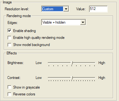
| Resolution level | Low | Medium | High | Very high | Custom |
| Resolution value (pixels) | 512 | 1024 | 2048 | 4096 | Any value between 64 and 4096 |
| None | Enables the view to display shading without any edges. Enable shading is forcedly checked and grayed. |
|
| Visible | Enables the view to show only visible edges (only for Image only mode) |
|
| Visible + hidden | Enables the view to show visible edges (continuous line) and hidden edges (dashed line) — (only for Image only mode). |
|
| Wireframe | Enables the view to show all edges with continuous line (only for Image only mode; and no shading permitted.) |
|