
![]()
File 3D Printing
If a 3D printer is installed on your computer, the 3D Printing command enables you to print an object directly from ThinkDesign using the 3D printing support in Windows 8.1.
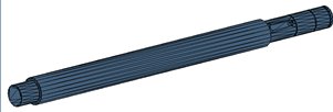
After starting the command, select the solids or meshes you want to print. The preview of the meshed entities is displayed.
In the Mode drop-down list, select the type of printing you want to perform:
If the check-box Layer for supports is checked, the entities lying in the selected layer are considered as supports by the 3D printer or in the AMF/3MF saved file.
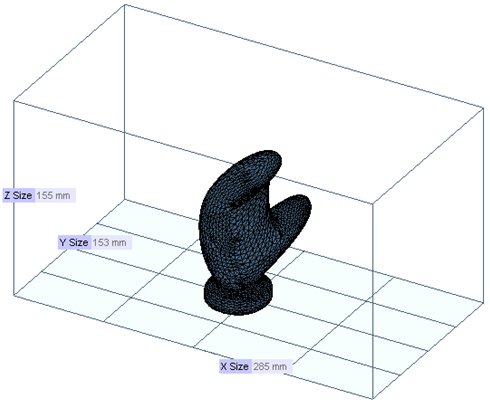
When the Mode is 3D Print, the Build volume can be displayed in the graphics area. It can be positioned onto the origin or so that the entity to print is XY centered and on the plate.
A message warns you if the entity to print is partially or completely out of the build volume.
The Properties button enables you to change the settings of the 3D printer.
You are enabled to navigate forward and backward among the selected entities using the arrows ( ) of the common ThinkDesign navigator.
Once positioned on the listed entity:
The Printability checks:
| Manifold | The meshed entity must be manifold to be printed. If it is not, the non-manifold edges are highlighted in pink on the mesh preview.
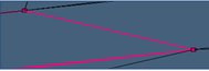 |
| Open | The meshed entity must be watertight to be printed. If it is not, the open edges are highlighted in green on the mesh preview.
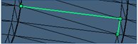 |
Under Options, it is possible to:
Under More Options, change the tessellation parameters used to mesh the selected entities. If Use current tessellation is checked, the selected entity will be meshed using its tessellation parameters. Otherwise the user can tune the following parameters:
| Tolerance of tessellation. |
| Show discontinuities (the tessellation to create the mesh takes into account the cusps on the solid). |
| Maximum edge length of the tessellation |
| Skip planar surfaces (to apply the maximum edge length only on curved surfaces and not on the planar ones). |
When a tessellation parameter has been changed, Update Mesh using the button ( ) on top of the selection list.