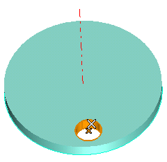
End selection by right-clicking and choosing Continue in the context menu. To change the selected feature, right-click on Base Entities in the selection list, choose Reset in the context menu and select another feature.
| Linear | Creates a linear pattern in one direction. |
| Angular | Creates an angular pattern about a single axis. |
| Linear-linear | Creates a linear pattern in two directions. |
| Linear-angular | Creates a linear pattern in one direction and then revolves those solids or features about an axis. |
| Angular-linear | Creates an angular pattern about an axis and then creates a linear pattern in one direction |
| Angular-angular | Creates an angular pattern about an axis and then revolves those solids or features about a second axis. |
Select Angular.
| Fit | Enables you to specify the number of copies and the linear or angular extension in which to fit those copies. |
| Fill | Enables you to specify the linear or angular step between the original and the first copy, and the linear or angular extension in which to fill those copies (with the number of copies determined by the number required to fill the extension). |
| Fixed | Enables you to specify the number of copies and the linear or angular step between the original and the first copy. |
| Inherit | Enables you to copy data from an existing pattern to be selected, automatically applying them to the pattern you are creating. |
Select Fill.
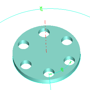
Choose Line and select the red axis as in the following illustration:
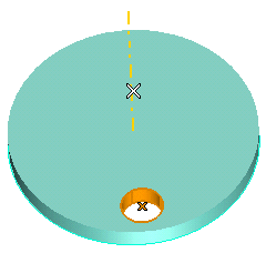
To change the selected axis, right-click on 1st Axis, choose Reset in the context menu and select another axis.
or
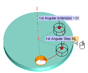
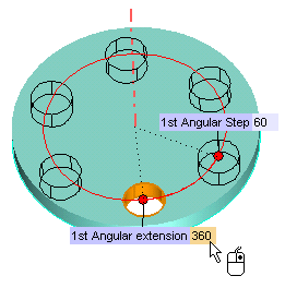
click and drag the handle to interactively set the angle.
or
click and drag the handle to interactively set the angle.
Only when patterning features — not a solid — , the Mode drop-down list is available, enabling you to select the method to create the pattern copies:
|
|||||
| Use the Simplified preview check box to control the way preview images of the copies are displayed: When selected, it shows preview images of patterns using simple X's. When not selected, it shows preview images of patterns using actual copied solids or features. Enabling the simplified preview can be very useful when the number of faces of the involved features/solid is high. When this number reaches 400, the program, after a confirmation request, switches to the simplified preview mode. | |||||
| Only when patterning a solid — not features — the Joined copies check box is available, to determine whether the copies are created as one solid or individual solids. |
 or
or  to confirm your selections and create the revolved pattern.
Click
 to discard your changes.