- Distance+45^
- Distance+Angle
- Distance+Distance
Note that you can apply the chamfer to all edges with tangency continuity to the selected edges by selecting the Tangency Chain check box under Group Options.
- If you chose Distance+45^ (to create a 45º chamfer):
- In the Distance mini-dialog, specify the distance from the edge.
- If you chose Distance+Angle:
- In the Distance mini-dialog, specify the distance from the edge.
- In the Angle mini-dialog, specify the chamfer angle.
- If you chose Distance+Distance:
- In the 1st Distance mini-dialog, specify the first chamfer distance.
- In the 2nd Distance mini-dialog, specify the second chamfer distance.
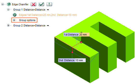
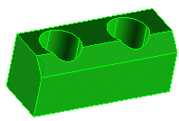
an arrow will be displayed. If you double-click on the arrow
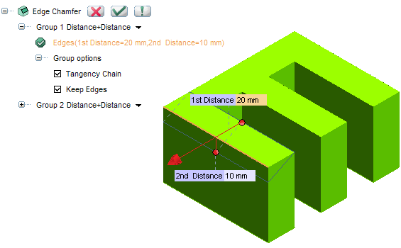
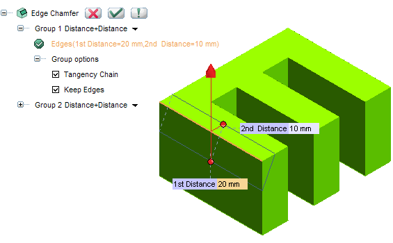
the chamfer direction will be inverted:
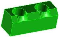
or clear the check box to extend the chamfer through any intersected edges.
 or
or  to confirm your selections and chamfer the selected edges. Click
  to discard your changes.