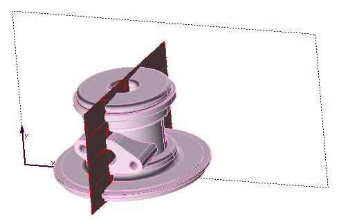
In order to define a section "on the model", the referenced model must contain a datum plane or profile that can be used to define the cutting plane.

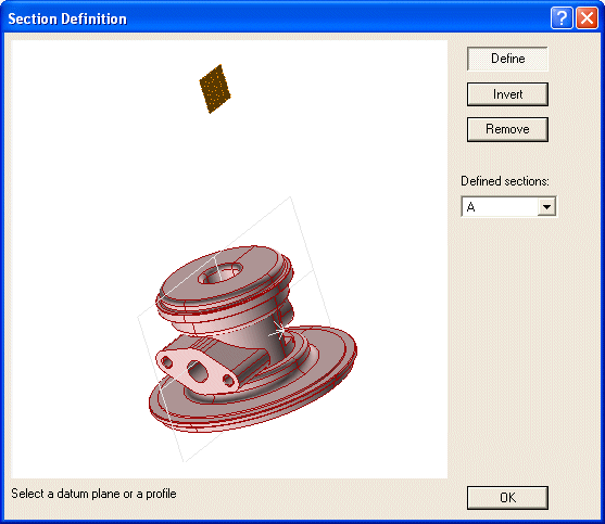
| 1 | When you start the Define on Model command, the program displays the Section definition dialog box. The referenced model is displayed. |
|
| 2 | To define a cutting plane line from a datum plane or profile in the referenced model,
click Define and then select the datum plane or profile. |
|
| 3 | As soon as you select the datum plane or profile,
the program adds the cutting plane to the image in the
Section definition dialog box and adds a section letter to the Defined Sections list. An arrow indicates the direction of the cutting plane.

|
|
| 4 | Click OK to complete the command. The cutting plane line can now be used to create sections. |