To insert a feature control frame proceed as follows:
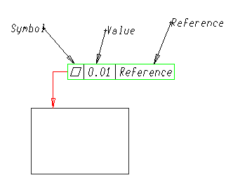
| 1 | In the Symbol drop-down list, choose the geometric tolerance symbol. |
| 2 | Select the Diameter Symbol check box to include a diameter symbol, if appropriate. |
| 3 | In the Value box, type or select the tolerance value. |
| 4 | In the Material Condition box, select a material condition, if appropriate. |
| 5 | To include datum references, click the Entity Properties node; in the Line type: drop-down list, select Datum reference. |
| 6 | You are prompted to select an entity. Click to select the entity to which you want to attach the feature control frame. |
| 7 | The program then prompts you to enter the positioning point. Click to specify the endpoint of the leader line. This prompt repeats, so that you can create multiple leader line segments. |
| 8 | When you have finished creating the leader line, end input.
|