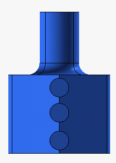
The drawing view obtained by the above model view on the right displays the holes not as circles, but as two separate semicircles, as you can see in the following image (file "RemoveOverlaps+HoleTable.e2"):
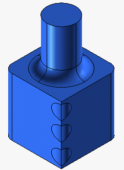
There are drawings in which holes might be represented using two separate semicircles rather then a whole circle. This may happen, for example, when a hole is created across an edge, like in the model shown in the following picture
(file "RemoveOverlaps+HoleTable.e3"):


The drawing view obtained by the above model view on the right displays the holes not as circles, but as two separate semicircles, as you can see in the following image (file "RemoveOverlaps+HoleTable.e2"):

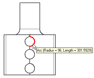
If you try to apply the Hole Table command and select the six semicircles representing the holes:
you will see that nothing is selected: the semicircles do not identify holes.
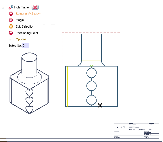
In order to successfully apply the Hole Table command, you will have to merge each couple of adjacent semicircles into the corresponding circles. To do this, you can take advantage of using the Remove Overlaps command.
| 1 | After starting the Remove Overlaps command, in the Select drop-down list choose Window and specify the two opposite corners as displayed in the picture below: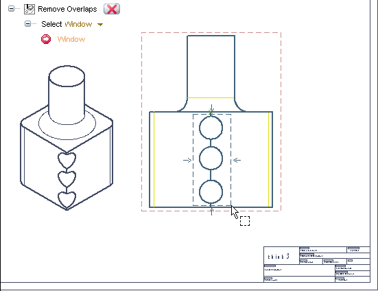 The semicircles are selected: 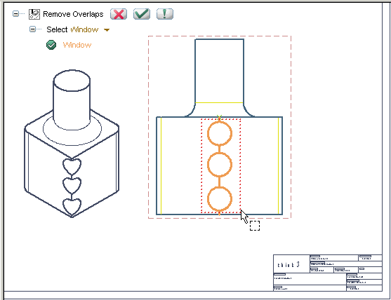
|
| 2 | Click  to apply the command. The following report is displayed: to apply the command. The following report is displayed:
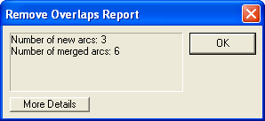 The six semicircles have been merged into the corresponding three circles. |
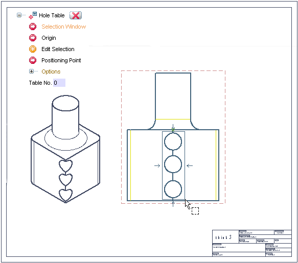
| 3 | Now you can start the Hole Table command and select the holes.
 |
| 4 | Specify the point to be used as the coordinate origin for computing the hole coordinates to be listed in the hole table.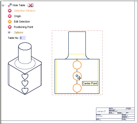 |
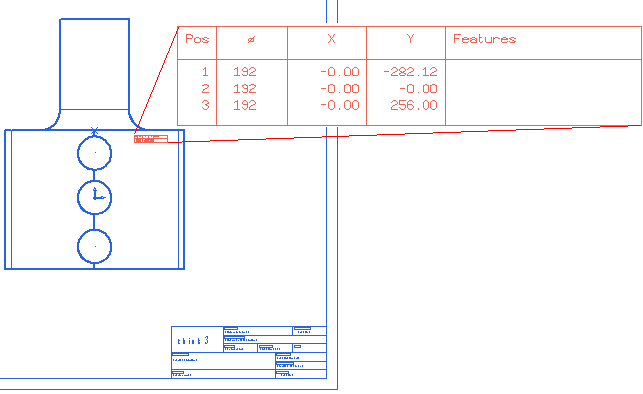
| 5 | Click  to confirm your selections and create the hole table. to confirm your selections and create the hole table. |
| 6 | To position the hole table, just drag it using the selection button of the mouse. Release the mouse button in the position where you want to place the hole table.
 |