Applying geometric transformations to selected interpolation points
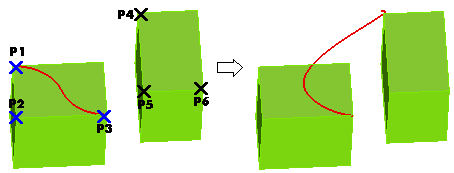
The Transform item under Tools in the selection list of the Curve Interpolation Points command enables you to apply a transformation to the currently selected points.
The curve shape will be updated dynamically while the transformation is being applied.
After selecting one or more interpolation points,
click on Transform under Tools in the selection list. The Transform dialog box will be displayed.
| Translate |
translates selected points |
| Rotate |
rotates selected points |
| Roto-translate |
rotates selected points about an axis and translates the axis at the same time |
| Mirror |
mirrors selected points about a plane of symmetry |
| Stretch |
stretches selected points |
| Multi-axis stretch |
stretches the parts of the curve defined by the
selected points with respect to two or three axes |
Translate
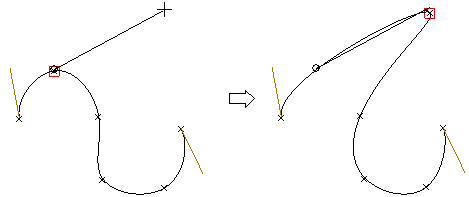
The Translate option of the Transform dialog box enables you to translate selected points.

You can define a translation by defining the translation vector. Select Vector and click on the two positions corresponding to the endpoints of the translation vector, or enter the vector components into the X, Y, Z adjacent boxes. To redefine the origin of the translation, select Origin and click in the desired position or enter the origin coordinates into the X, Y, Z adjacent boxes.
Rotate
The Rotate option of the Transform dialog box enables you to rotate selected entities.

A rotation is a transformation which rotates selected entities by a specified angle about an axis called the axis of rotation.
You can define a rotation by:
- Defining the Axis (select an item in the drop-down list. It can be one of the coordinate axes, an existing line or a line defined by indicating two points)
- Entering the rotation value into the Angle box
- Defining the the origin of the rotation, by selecting Origin and clicking in the desired position or entering the coordinates into the X, Y, Z adjacent boxes.
Roto-translate
The Roto-translate option of the Transform dialog box enables you to rotate selected entities about an axis and translate the axis at the same time.

You can define a roto-translation proceeding as follows:
- Under Roto-translate, click the First reference button, and then specify three points in the model which identify a reference system to be roto-translated, as follows:
- Origin point
- X-direction
- Through-point for XY-plane (positive Y) — the axis from the origin to this point is the Y-axis
- Click the Second reference button, and then specify three points in the model which identify the roto-translated reference system, as follows:
- Origin position: the starting point of the resulting reference system
- X-direction — the axis from the origin to this point is the X-axis
- Through-point for XY-plane (positive Y) — the axis from the origin to this point is the Y-axis
Mirror
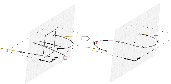
The Mirror option of the Transform dialog box enables you to mirror selected entities about a plane of symmetry.
A mirror is a
transformation which corresponds a general point P to a point P' lying on a
perpendicular line through P on a pre-set plane known as the plane of symmetry
and at a distance from this plane equal to that of P. A reflection is completely
defined when the plane of symmetry is identified.
You can define a mirroring transformation as follows:
- Specify the plane by selecting one of the options of the Plane drop-down list (it can be either a plane defined as normal to one of the coordinate axes or to a line, or an existing plane)
- Click the Origin button and then indicate the point in the model to be used as origin or type the origin coordinates into the X, Y and Z boxes.

Stretch
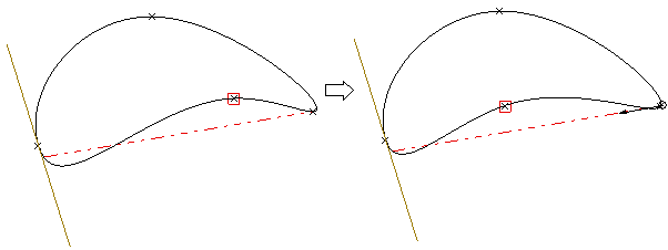
The Stretch option of the Transform dialog box enables you to stretch selected entities.
A stretch is a transformation which deforms the
selected entities by stretching them in the specified direction, with respect to
a specified origin and in the proportion determined by a user-specified scale
factor.
You can define a stretch transforamtion as follows:
- Type the scale factor value for the stretch in the Scale box.
- Click the Origin button and then indicate the point in the model to be used as origin for the stretch or type the stretch origin coordinates in the X, Y and Z boxes
- Specify the stretch axis by selecting one of the following options in the Axis drop-down list (It can be one of the coordinate axes, an existing line or a line defined by indicating two points).

Multi-axis stretch
The Multi-axis stretch option of the Transform dialog box stretches the
parts of the curves defined by the selected points with respect to two or three
axes.
You can define a multi-axis stretch transformation as follows:
- Set the reference system for the the stretch axes by selecting the corresponding item in the Reference drop-down list
| Work Plane |
The Work Plane reference system |
| User defined |
A user defined reference system. To define it, do the following:
- Click Define reference
- Enter the system origin position
- Enter a point defining the X axis direction (i.e.: from the specified origin to this point)
- Enter a through point for the XY plane, defining the positive direction for the Y axis.
|
- Define the axes for the multi-axis stretch operation by selecting the corresponding item in the Axes drop-down list:
| XY |
axes X and Y of the selected reference system |
| XZ |
axes X and Z of the selected reference system |
| YZ |
axes Y and Z of the selected reference system |
| XYZ |
axes X, Y and Z of the selected reference system |
- Type the scale factor value for the stretch in the Scale box.
- Click the Origin button and then indicate the point in the model to be used as origin for the stretch or type the stretch origin coordinates in the X, Y and Z boxes.
Whichever the transformation you selected, double-click to apply it.


