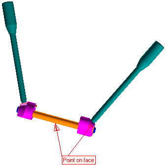
The point of interest here is to check the mating possibilities between these two components.
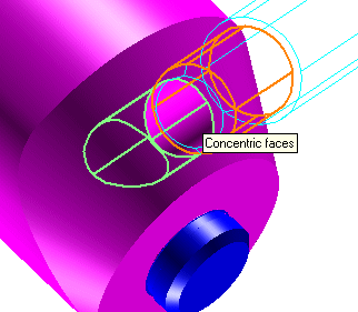
A closer look at the components show that you can have a Concentricity constraint between the lever and hole on the cam.

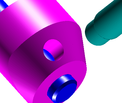
For the second constraint you do not have a plane face available for mating. Note here that the shaft (Component in Blue), intercepts the hole on the Cam.

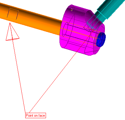
To deal with this kind of situation, you have the Point on face constraint.

You can select the vertex on the lever as shown and place a constraint of Type, On face by selecting the surface of the shaft (highlighted).
| Note
If the geometry you are working on does not provide for a vertex, you can use a datum point instead. |