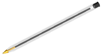
composed of a tip, an ink barrel, a transparent body and a rear end cap.
Suppose you are handling a ballpoint pen,
composed of a tip, an ink barrel, a transparent body and a rear end cap.
You are in charge of inserting the adequate Symbolic References in the different component parts, in order to facilitate mating and, particularly, component replacing.
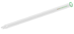
The goal of this example is assigning the same Symbolic References to the rear end cap
and to the body.
See also Creating a master model for details on how to create the assembly of the ballpoint pen components with the Symbolic References necessary to mount them correctly, by using thinkconfigure.
Models related to this job are rear end cap.e3 and stilo.e3, available in the samples folder.
Note that the procedure described below also applies to the Redefine command. In actual fact, the Redefine command displays the same selection list and enables you to modify an existing Symbolic Reference. The only difference you get in the selection list is the  (Apply) one, enabling you to update and rebuild the model including the modified Symbolic References. (Apply) one, enabling you to update and rebuild the model including the modified Symbolic References.
|
After starting the think3 application, proceed as follows.
| 1 | Load the rear end cap.e3 model and select the bottom face that will be placed on the top face of the transparent body and you will name "CapShoulder".
|
|
| 2 | Select the Insert  Symbolic Reference Symbolic Reference New command. The following selection list is displayed in the graphics area: New command. The following selection list is displayed in the graphics area:
The Entities or Points item in the selection list shows the green marker, since you already selected the entity that you are declaring to be a Symbolic Reference.
|
|
| 3 | In the mini-dialog box, type in the name of the Symbolic Reference you chose:
|
|
| 4 | Click  (Apply) to confirm your selection and select the following entity (the external cylindrical surface of the cap, that will mate the internal cylindrical surface of the body): (Apply) to confirm your selection and select the following entity (the external cylindrical surface of the cap, that will mate the internal cylindrical surface of the body):
|
|
| 5 | In the mini-dialog box, type in the name of the new Symbolic Reference, "CapHole":
|
|
| 6 | Click  (OK)to confirm your selections and create the Symbolic References, as you can see in the Model Structure. (OK)to confirm your selections and create the Symbolic References, as you can see in the Model Structure.
 to discard your changes. to discard your changes.
|
|
| 7 | Repeat the same steps for the transparent body. Load the stilo.e3 model and attach the Symbolic Reference "CapShoulder" to the top face of the body solid:
|
|
| 8 | Now attribute the Symbolic Reference "CapHole" to the internal hole of the body solid:
|