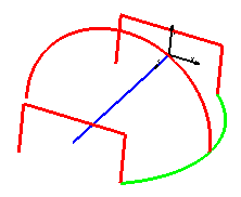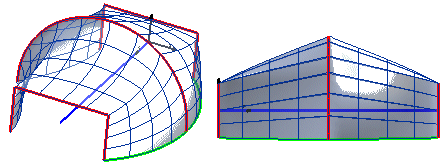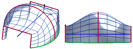
In the case of more than two boundary curves, you can control the shape of the surfaces which will form the final surface where they meet, that is to say at the boundary curves.
Let us see what happens to the model of the following illustration (to try it, load file "spsrf_blending.e3") where the blue curve is the spine, the red profiles are the boundaries and the green curve is the drive.
Select the type of blending to be applied to the surfaces along the boundaries in the Blending drop-down list under More Options:
| Linear | Creates the surfaces applying no tangency constraint. Looking at a section obtained from the placement plane of the spine-profile, you will see that:
 |
| Hermite | Applies tangency continuity to the surfaces between two subsequent pairs of boundaries (at the shared boundary). |
| Smooth 1 | Interpolates the endpoints of the boundary profiles with a 3D spline in relative coordinates. This means that instead of the endpoints specified in absolute coordinates, the spline interpolates points whose x- and y-coordinates are equal to the coordinates of the projections of the endpoints, each in the plane of the corresponding boundary profile (remember that the profile is orthogonal to the spine profile), while the third coordinate is equal to the value of the parameter of the spine profile at the point where it intersects the corresponding boundary profile. This procedure is equivalent to interpolating the endpoints of the boundary profiles when these are positioned on the spine profile obtained by "rectifying" the real boundary profile. |
| Smooth 2 | Interpolates the endpoints of the boundary profiles with a 3D spline. In this case, the lateral surfaces maintain curvature continuity at the boundary profiles. |