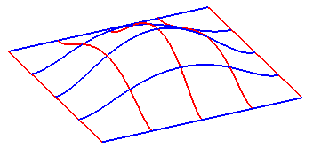
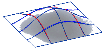
As you can see, the curves in the above model identify two orthogonal sets of parallel curves (the blue ones and the red ones).
Suggestion: to make curve selection easier, turn the viewing mode to Wireframe.
Once you have started the Lofted Surface command, you can proceed as follows (please note that you can follow this step-by-step example by loading file: "UVcurve.e3").

As you can see, the curves in the above model identify two orthogonal sets of parallel curves (the blue ones and the red ones).
Suggestion: to make curve selection easier, turn the viewing mode to Wireframe.
| 1 | To obtain an associative surface, that is an open solid — a Skin — retaining a link to its base curves, so that if you modify such curves the surface will be modified accordingly, check the Associative Mode box. See "
Associative Surfaces (Skins)" for details. |
| 2 | In the Select As drop-down list, select the Grid option. |
| 3 | Select the blue curves as the first set of curves (please note the selection order is completely free):
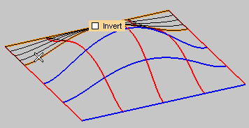 Once you selected all the curves of the first set, end selection: 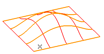 To change the selected curves (for example if you selected the wrong ones by mistake), right-click on Boundary Set A in the selection list, select Reset and perform selection again. |
| 4 | Select the red curves as the second set of curves (please note the selection order is completely free):
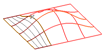 Once you selected all the curves of the second set, end selection: 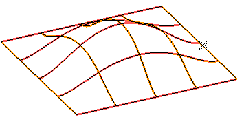 To change the selected curves (for example if you selected the wrong ones by mistake), right-click on Boundary Set B in the selection list, select Reset and perform selection again. Please note that if you select More Options, the Type drop-down list is set to Default, which is the default value. With the previous selection, the current surface type automatically determined is Grid. |
 or
or  to confirm your selections and create the surface.
 to discard your changes.