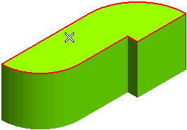
To change the selected face, click on Face in the selection list and select another face.
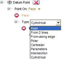
- Point — the datum point is initially positioned in the point you chose when you selected the face.
- To move the datum point, click on Point in the selection list and then click to select a new position. You can also move the point by dragging its handle.
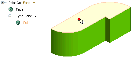
- To move the datum point, click on Point in the selection list and then click to select a new position. You can also move the point by dragging its handle.
- From 2 lines — the position of the datum point is based on the distances from two (history based) lines which can be:
- Edges, even not belonging to the same faces
- Datum lines
- Lines belonging to profiles.
- In the 1st Distance mini-dialog, specify the distance from the first line, or drag the datum point center-point handle. To specify a different line as the first one, click on First Line in the selection list and then select the line.
- In the 2nd Distance mini-dialog, specify the distance from the second line, or drag the datum point center-point handle. To specify a different line as the second one, click on Second Line in the selection list and then select the line.
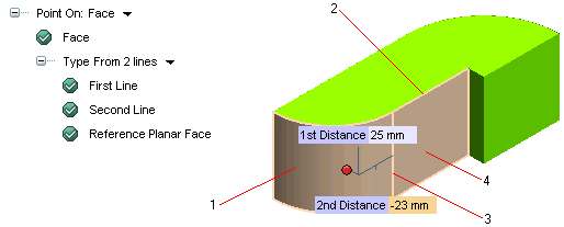
1 — the selected Face
2 — the First Line
3 — the Second Line
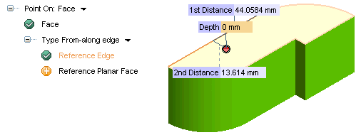
4 — the Reference Planar Face - From-along edge — the position of the datum point is based on the distance from one boundary edge of the face in which datum point is to be created or on the Reference Planar Face (see below) and the distance along that edge.
- In the first 1st Distance mini-dialog, specify the distance along the selected edge to the point, or drag the point handle. To specify a different reference edge, click on Reference Edge in the selection list and then select a new edge.
- In the second 2nd Distance mini-dialog, specify the distance perpendicular from the selected edge to the point, or drag the datum point handle.
In the selection list the Reference Planar Face is displayed: the selection of a planar face is optional if the face is planar, mandatory if the face is not planar.
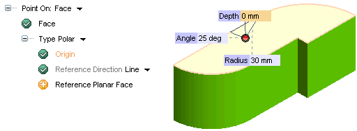
- Polar — the position of the datum point is based on its radius distance from a polar origin and the angle from a reference line.
- Origin — the origin is a mandatory selection element, whenever possible, the default origin will be automatically selected based on the face selection. You can change the origin by clicking on Origin and specifying another point.
- Reference Direction — you will have to specify the reference direction (as an existing line or the one identified by two points to be selected); whenever possible, the default reference direction will be automatically selected based on the face selection. You can change it by clicking on Reference Direction and specifying another direction.
- In the Radius mini-dialog, specify the radius from the origin to the position of the datum point, or drag the datum point handle.
- In the Angle mini-dialog, specify the angle from the reference line to position of the datum point, or drag the datum point handle.
In the selection list the Reference Planar Face is displayed: the selection of a planar face is optional if the face is planar, mandatory if the face is not planar.
- Cartesian
the datum point is defined through its X, Y coordinates measured starting from an origin and using a reference X-axis.- Origin — the origin is a mandatory selection element, whenever possible, the default origin will be automatically selected based on the face selection. You can change the origin by clicking on Origin and specifying another point.
- Reference Direction — you will have to specify the reference direction (as an existing line or the one identified by two points to be selected); whenever possible, the default reference direction will be automatically selected based on the face selection. You can change it by clicking on Reference Direction and specifying another direction.
- Reference Planar Face — the selection of a planar face is optional if the face is planar, mandatory if the face is not planar. You can change it by clicking on Reference Planar Face and specifying another face.
- Delta X and Delta Y — are the distances (to be specified) of the point from the origin along the selected Reference Direction and in the direction orthogonal to it.
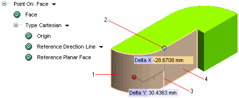
1 — the selected Face
2 — the selected Origin
3 — the selected Reference Direction
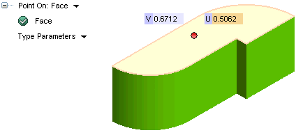
4 — the selected Reference Planar Face - Parameters — the position of the datum point is based on the u and v parameters of the face in which the datum point is to be created.
- In the U mini-dialog, specify the U parameter, or drag the point handle.
- In the V mini-dialog, specify the V parameter, or drag the point handle.
- Intersection — the position of the datum point is based on the itersection of a selected line and the face on which the datum point is to be created.
- In the Axis drop-down list, select one of the following:
- Line
— select the line or edge intersecting the selected face in the desired position for the datum point. - 2 Points
— select the two points that define the axis intersecting the selected face in the desired position for the datum point. 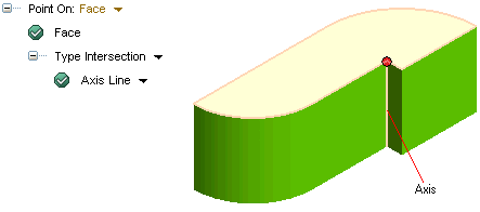
- In the Axis drop-down list, select one of the following:
- Cylindrical
- Start the Datum Point command.
- Set the Point On: option to Face.
- Select a face of any solid with an axial symmetry.
- Change the Type option to Cylindrical and you can vary the Angle and Distance to specify the location of the point.
- The sub options Radial direction and
Reference to origin specify the direction and location of the point over the face.
Datum points can be inserted on the faces of solids having an axial symmetry (for example, on a cylindrical or conical face) with the Cylindrical coordinates (
 ) as their reference.
For a quick introduction to adding a datum point using the Cylindrical coordinates, follow these steps:
Consider the following image:
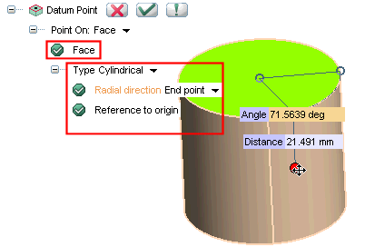
When you select a cylindrical face (as shown above), the radius r (of the point’s cylindrical coordinate) is automatically defined as the radius of that face and cannot be changed. For the Reference to origin option, select the face whose center is considered as the origin for the cylindrical coordinate system. In the above example, the center of the top face of the cylinder is selected as origin. The
Radial direction option can be anyone of the
2 points,
Line, or
End point. It acts as the reference for measuring the angle ( ) of the point coordinate. Once the radial direction and origin are set, the
Angle gets defined for the cylindrical coordinate system. The
Distance defines the depth Z of the coordinate system.
Consider another example:
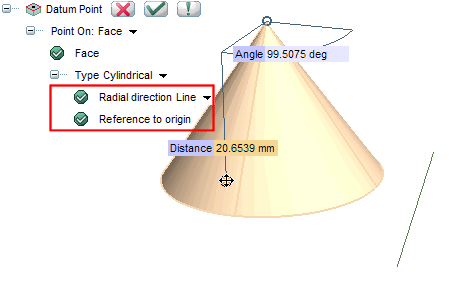
Here the datum point is added on an axially symmetric conical face and for it all the 3 cylindrical coordinates  can be varied. The origin is the vertex of the cone and a line external to the cone defines the radial direction. Note that, the radius changes with a change in the Distance value(from the vertex to the base of cone), unlike the previous example, in which the radius was a constant.
 or
or  to confirm your selections. Click
  to discard your changes.