Overview of Nodes
A node is an intersection of two or more frame parts. After the initial selections of the predefined profile and the cross section parameters, the following two options enable you edit and apply the different properties to a node.
The Joint Type: drop-down list enables you to select the type of node. The following are the options available.
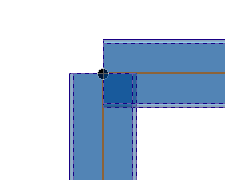
- Disjoined: The two intersecting frame parts are not joined as shown in the image below:
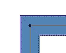
- Miter: The two frame parts are joined with a 45 degree angle as shown in the image below:
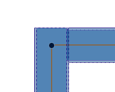
- Butt: The longest of the two frame parts is kept intact and the other is trimmed as shown in the image below.
The Trim Mode: drop-down list enables you to trim the frame parts at the node. The following are the methods.
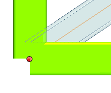
- First face: The frame part is trimmed to a selected face of another frame part as shown in the image below:
- Simplified faces: The Frame part is trimmed to the selected faces of the frame parts as shown in the image below:
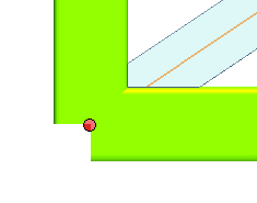
- All faces: It is almost same as that of the Simplified faces. Here the Frame Part is trimmed to the real surface of the selected frame part (excluding the curvature on the edges).
Additional Node Options
After selecting the line specification, the cross section parameters and the type of node, the following options are available to do further operations on a single node. Click on a node handle and the following additional options are displayed in the selection list.
Node X: A new node is displayed with the X representing the node number you have clicked. By expanding the node ( ) the following options are available.
- Trim part Y check box: When selected it enables you to trim the frame part associated with the selected node. The number of Trim part displayed in the selection list depends on the number of frame parts that form the node. The Y is replaced by the number in increasing order corresponding to the frame parts.
The trimming of the frame part can be done by selecting the options in the drop-down list.
- By Faces: The trimming of the frame part is done by selecting a face using the Faces selector.
- By Parts: The trimming of the Frame part is done by selecting a associated frame part using the Parts selector.
- Offset Z: The offset edit box is displayed on the frame parts in the graphics area. This enables you to specify the value by which the material of the frame part can be added or removed. The Z represents a number in increasing order of frame parts that can be offset from the selected node.


![]() ) the following options are available.
) the following options are available.