Creating a Frame Structure
In this tutorial you will create a frame structure with two different cross section frame parts. Open the frame_insert.e3 file available in the Samples folder of your think3 installation and follow the steps given below.
- Start the Frame Parts command and select a line for the Beams selector.
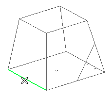
- From the Line drop-down list select Steel - hot rolled - UNI. The catalog corresponding to the selected line specification is available by expanding the Line node (
 ).
).
- From the Sections drop-down list select the HEA.
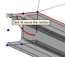
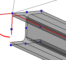
- The frame parts can be aligned by selecting the control points on the cross section with respect to the selected line. For this tutorial the cross section is aligned as shown in the image below.
- Select the other lines to complete the profile. Click on the Apply
 button in the selection list to create the frame parts.
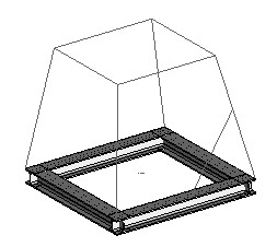
- Click on the Beams selector and select a line as shown in the image below
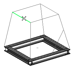
- Select Square Bar from the Sections drop-down list. Open the Sections node (
 ) and select 100*4 from the dialog box displayed.
- Select the lines to complete the square profile.
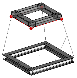
- Under More Options, select Miter from the Joint Type: drop-down list.
- Click on the Apply
 button to create the frame parts.
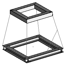
- Click on the Beams selector and click the line as shown in the image below:
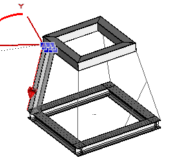
- Select the Square Bar from the Sections drop-down list.
- Set the alignment of the frame part by expanding the Alignment node. In this tutorial, select the Line option from the Y Axis drop-down list. Click on the Y Axis selector and select the line as shown in the image below:
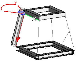
- Under More Options, select the Simplified faces from the Trim Mode: drop-down list.
- Select the remaining lines and Click on the OK button to complete the Frame structure. All the Frame Parts are listed in the Model Structure.
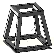

 button in the selection list to create the frame parts.


 button to create the frame parts.


 button in the selection list to create the frame parts.


 button to create the frame parts.


